Considerations for Designing High Power RF and Microwave Passive Components
 2023-04-11
RF and microwave passive components are burdened by many design constraints and performance specifications. Depending on the power requirements of the application, the material and design performance requirements can increase significantly. For example, in high power telecom and military radar/jamming applications, high performance levels are required along with very high power levels. Many materials and technologies cannot withstand the power levels required for these applications, so specialized components, materials and technologies must be used to meet these extreme application requirements.
High levels of radio frequency and microwave power are invisible, difficult to detect, and capable of generating incredible amounts of heat in a small area. Typically, overpower stress is only detected after component failure or complete system failure. This situation is frequently encountered in telecom and aerospace/defense applications because the use and exposure to high power levels is necessary to meet the performance requirements of these applications.
High enough RF and microwave power levels can damage components in the signal path, which can be the product of poor design, material aging/fatigue, or even strategic electronic attack. Any critical system that may encounter high power RF and microwave energy must be carefully designed and supported with components specified for the maximum potential power level. Other issues, such as RF leakage, passive intermodulation distortion and harmonic distortion, are exacerbated at high power levels because more consideration must be given to the quality of the components.
Any interconnect or component with insertion loss has the potential to absorb enough RF and microwave energy to cause damage. This is why all RF and microwave components have a maximum power rating. Typically, since RF energy has several different modes of operation, it will be rated for continuous wave (CW) or pulsed power. Additionally, since the various materials that make up RF components can change their behavior at different powers, temperatures, voltages, currents, and age, these parameters are often also specified. As always, some manufacturers are more generous with the specified functions of their components, so it is recommended to test specific components under actual operating conditions to avoid field failures. This is a particular concern for RF and microwave components because cascading failures are common.
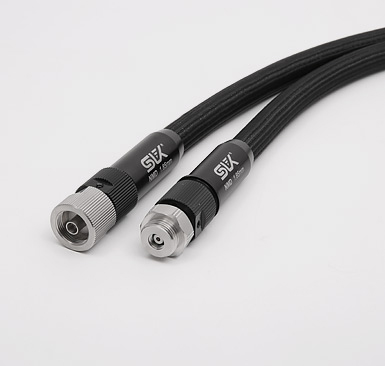
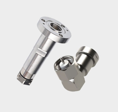
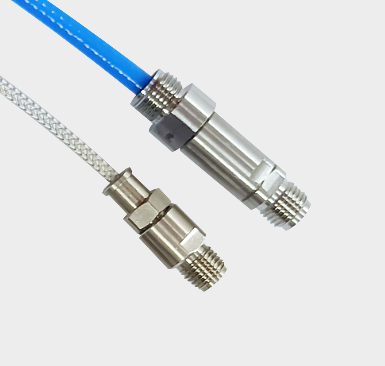
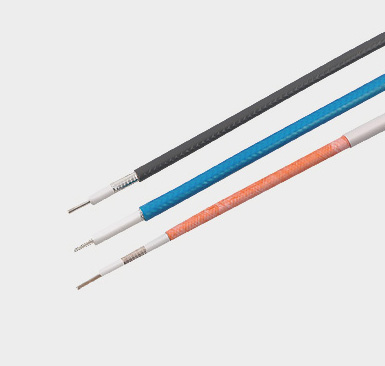
Depending on frequency, power level and physical requirements, coaxial or waveguide interconnects are used for high power RF and microwave applications. Both technologies scale in size with frequency, requiring higher precision materials and fabrication to handle higher power levels. In general, waveguides tend to be able to handle higher power levels than comparable coaxial technologies as a product of the way RF energy travels through waveguides with an air dielectric. On the other hand, waveguides are generally more expensive than coaxial technology, custom installed and narrowband solutions.
That said, for applications requiring lower cost, greater installation flexibility, higher signal routing density, and moderate power levels, coaxial technology may be the preferred choice. Also, there are more component options using coaxial interconnects over waveguide interconnects due to reduced cost and size. Although broadband and generally more direct to mount, waveguide technology often outperforms coaxial in terms of high performance, ruggedness, and reliability. Typically, these interconnect technologies are used in series, with the highest power and fidelity signals routed through waveguide interconnects where possible.
An important characteristic to note with coaxial technologies is that their power and voltage related dielectric breakdown is much lower than similar frequency waveguide interconnects. This may be acceptable if weight and cost are high concerns. However, issues with material outgassing and changes in material properties at high temperature and pressure can reduce the viability of coaxial technology in aerospace applications.
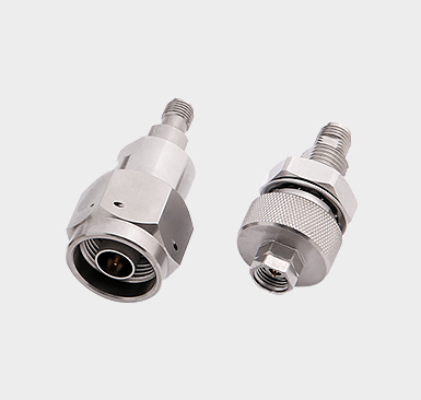
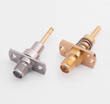
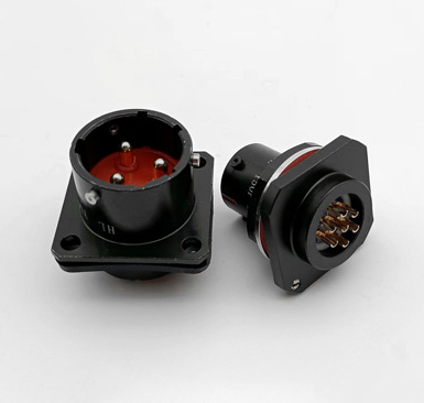
Since each adapter and termination introduces unwanted insertion loss and reflections, careful selection of the correct components can prevent unwanted signal degradation and possible damage to sensitive electronics Adapters and terminations come in many forms, usually coaxial or waveguide , for high power applications. Also, adapters can be more complex, as the size and type can be different on either end of the adapter. Additionally, the adapter itself may introduce turns or bends.
The power and frequency range of the adapter must be carefully checked, especially if the adapter is a waveguide-to-coax conversion. Waveguides can naturally only enable band-wide bandwidth to be transmitted with high signal fidelity, where coaxial technology only has a cutoff frequency. However, different coaxial connector types also have different power and frequency capabilities. If the adapter is a transition between two different coaxial connector types, frequency, power handling, PIM, insertion loss and other parameters will be affected.
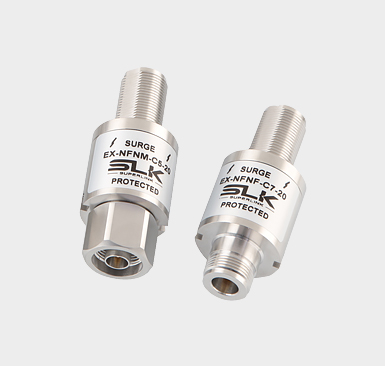
Endpoints bear the brunt of depleting potentially extreme RF energy within the device. Typically, terminals for high power applications will have heat dissipating metal bodies and possibly forced air thermal management. Impedance matching and voltage standing wave ratio (VSWR) of the terminations are absolutely critical, as unpredictable reflections can lead to overpower and overvoltage conditions in upstream electronics. In the case of shunting a High Power Amplifier (HPA) to a terminal that does not meet adequate VSWR specifications, this can be dangerous as it can permanently damage the HPA.
Like terminators, attenuators are designed to dissipate RF energy within the body of the device without any unwanted signal distortion or reflections. There are fixed and variable attenuators. For most very high power applications, fixed attenuators are more common. Like terminators, they can be waveguide or coaxial. Alternatively, the attenuator can be an adapter to a different size coaxial connector size, although this is rarely done with waveguide connectors.
Depending on the amount of power the attenuator is designed to dissipate, a metal radiator will usually surround the body, or even forced cooling is an option. The higher the frequency, power handling and attenuation, the RF energy is converted to heat. When installing an attenuator, it is critical to ensure that the attenuator has adequate ventilation and is not mounted close to other heat dissipating electronic equipment.
Since filters can act as band-selective attenuators or reflectors of out-of-band signals, it is necessary to consider the type of upstream electronics and the signal entering the filter. Absorptive filters will absorb RF energy from out-of-band signals and convert it into heat. Among them, reflection filters redirect the RF energy back to the source. This type of filter can damage sensitive upstream electronics due to overpower or overvoltage. Depending on filter technology and construction, the power handling capability of a filter is usually highly frequency dependent.
Like most RF and microwave components, higher frequency components have lower power thresholds than their lower power counterparts. The relative size and materials of the filters will have a significant impact on power and frequency limitations. The passband of the filter naturally attenuates the signal slightly, so the passband characteristics are as important as the out-of-band filter characteristics in terms of RF energy absorption or reflection.
Directional couplers have many of the same concerns and constraints as adapters, with the added complexity of built-in termination or forward/reverse coupled signal paths. Also, the coupled signal path of the directional coupler is hundreds, thousands or tens of thousands of times less RF energy than the main propagation line. Due to the significantly reduced power levels on the coupled line, even for high power waveguide couplers, the coupled line is usually a coaxial connector. This is clearly not the case for hybrid couplers or 3dB 90° hybrid couplers, which evenly distribute the power of the signal in two equal RF signal paths.
Typically, directional couplers are designed to have very low insertion loss and reflection. At high power levels, the coupling method can introduce significant insertion loss and reflections if not precisely designed. Another factor to consider is the loading of the coupled lines. Although at low power levels a simple termination may suffice. However, at higher power levels, any mismatch or reflection can cause significant power to be fed into the main signal path. Also, depending on coupling strength, the termination of a directional coupler may require higher power handling than its low power counterpart.
Much like directional couplers, power splitters split RF signal energy along multiple paths. Among them, the power combiner feeds the RF signal energy into a main path. The issues with insertion loss and reflections are much the same with power splitters/combiners as they are with directional couplers. The main difference is that the power splitters/combiners are usually at approximately equal power levels, but not in phase. As a by-product, any impedance or VSWR mismatch in the connection or feeder may cause undesired signal degradation, phase deviation and reflections. Some power splitters/combiners have either the input or output as a waveguide or coaxial connection, and the input and output use different connector sizes or technologies.
PIM has a significant impact on wireless network performance, especially for high-power RF electronics. Since PIM is often difficult to determine in a complete passive device system, if PIM is a design issue, having high accuracy and low PIM passive components may be the first step in ensuring a lower PIM threshold. Any nonlinearity in the material or environmentally induced nonlinearity can lead to high levels of PIM.
Whether it is surface defects, microcracks or dissimilar material connections, high power levels often exacerbate the nonlinear effects that lead to PIM. Since high power applications are often also associated with more extreme environments, temperature variations, vibration and material aging can also contribute to non-linearities that lead to PIM. To reduce PIM response, each individual connection and component can be verified to operate with a reduced third-order intercept point, resulting in lower distortion. PIM response can also be confirmed after installation through rigorous post-assembly testing.
High power levels at high frequencies tend to cause dissipation of RF energy in non-ideal surfaces and materials. Dissipation of RF energy to most surfaces causes heating. RF heating can cause material changes in peak power operation or material degradation over several cycles of use.
Understandably, temperature and RF power level specifications for equipment should be kept within reasonable limits. Since many manufacturers are very optimistic about the performance of their products, it is reasonable to allow as much power and thermal headroom as possible within other design constraints. This is especially important in critical applications where downtime cannot be tolerated, as thermal stress can lead to thermal runaway, which can lead to rapid equipment failure.
Other environmental factors, such as moisture ingress and shock/vibration, can also temporarily reduce a component's power and heat-handling capabilities. Thorough testing of high power components in salt spray, temperature and mechanical stress test rigs is often used to validate component designs for extreme cases of certain applications.