Up to 110GHz! Detailed explanation of 1.0mm RF connector
 2023-06-01
The 1.0mm connector has been born for 32 years! In 1989, the precision connector standard committee IEEE287 defined the interface of the 1.0mm connector.
The 1.0mm connector has DC-110GHz ultra-wideband characteristics, which makes the test easier; in the past, multiple connections to the system were required, but now multiple tests can be completed with one connection.
The EEE standard defines two levels of 1.0mm connectors, laboratory precision LPC and ordinary precision GPC.
Ordinary precision grades are mainly used for connectors and cable assemblies.
The main difference between the two grades is the interface of the connector: the strictness of requirements such as cleanness, flatness, and interface depth.
Because the frequency is as high as 110GHz, the requirements for 1.0mm connectors are very strict. Whether it is ordinary precision GPC or laboratory metrology LPC, there is no room for tolerance.
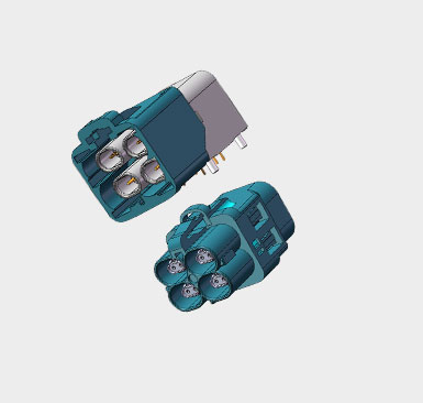
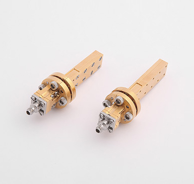
The name of the 1.0mm connector is similar to 2.92mm, 1.85mm, etc., which is the size of the inner diameter of its outer conductor.
The 1.0mm interface is defined as 1.0mm outer conductor inner diameter, air dielectric, 50 ohm impedance and 0.434mm center conductor outer diameter. The outer diameter of the center needle of the female head is 0.25mm. Both LPC and GPC female head needles have a slot design. The wall thickness of the female head can only be about 0.09mm, which requires very high requirements for materials and machining.
Accurately measuring 1.0mm connectors requires high-quality, high-precision calibration kits.
Generally speaking, Yawani uses OPEN, SHORT, and LOAD as calibration parts.
However, broadband fixed loads with low reflection, VSWR<1.03 (-30dB return loss) are very difficult to achieve, and sliding loads are required.
However, for a connector size of 1.0mm, it is impractical to make a sliding load. It is either too expensive, or the product is too fragile, and it is easy to damage or change parameters if there are too many times of sliding.
High-precision measurements at high frequencies (above 50 GHz) can only be achieved by using offset shunts.
Using modern finishing technology, the size, flatness and surface finish of the offset short circuit can be precisely controlled.
Multiple offset shorts can be used to cover the 50-110GHz frequency range. The part below 50GHz can use traditional OPEN, SHORT, LOAD calibration parts.
At 110GHz, the wavelength in the air is only 2.72mm.
Therefore, to obtain good accuracy in offset short calibration, precise control of the length of the offset and the depth of the pin is necessary.
The offset length control accuracy needs to reach ±0.005mm, which is really difficult for traditional testing methods.
Accurately measuring pin depth requires a new set of methods, and optical methods used in recent years have proven effective.
The offset length control accuracy needs to reach ±0.005mm, which is really difficult for traditional testing methods.
The traceability of the calibration parts finally goes back to the size standard.
It is relatively straightforward to measure the outer diameter of the center conductor, and the corresponding gauge can also be realized.
However, the accuracy of commercial 1.0mm gauges is still lacking, so there is a need for specialized metrology grade gauges.
But the size of this gauge is also quite challenging. Its dimensional accuracy tolerance must be controlled within 1/5 of the LPC joint accuracy, and the LPC accuracy is ±0.003 mm, so you can imagine the difficulty. At the same time, the measurement of the accuracy mentioned in this article also needs to rely on higher-precision measurement tools, otherwise it is meaningless to be unable to measure.
So which frequency bands are the DC-110GHz calibration finally divided into?
First of all, the frequency band below 50GHz uses the traditional OPEN, SHORT, LOAD method; 50-110GHz uses the offset short circuit method, which is divided into two frequency bands during implementation: three offset short circuit devices (length 1.30, 2.45 and 3.00mm) for 50-75GHz, and three other lengths (1.30, 1.825 and 2.45mm) for 75-110GHz.
The initial 1.0mm connector application is relatively small. The first 1.0mm interface product was born in 1993: a set of cable and waveguide coaxial converters used to test the chip probe system. Germany Rosenberg, an IEEE287 member unit, released their first 1.0mm connector and adapter in 1995. With the birth of HP's first special 85GHz test system and Cascade Microtech's probe system in 1996, the pace of 1.0mm product development began to accelerate. After HP released the 8510XF vector network analyzer, 1.0mm related products and accessories have sprung up like mushrooms.
A few cases: Microtech's ACP110 chip probe, GGB's probe, Rosenberger's 0.047-inch 1.0mm cable assembly and calibration parts
By around 2000, 1.0mm connectors had become widely accepted in the mmWave measurement community.
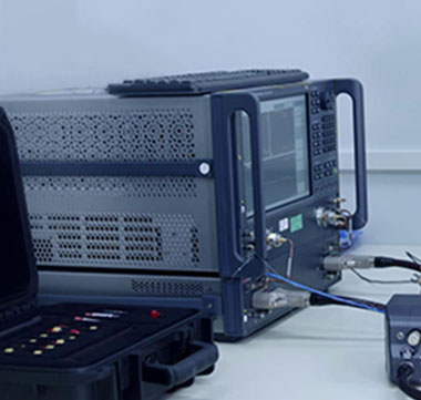
With the help of HP 85059A calibration and verification parts and HP 8510XF vector network analyzer at that time, it has been possible to obtain accurate and repeatable 110GHz products, such as connectors and various accessories.
The 1.0mm outer conductor part is designed to be reinforced and reinforced, but in order to achieve a good test structure, engineers have to be extra careful when connecting the 1.0mm connector, because its heart is too fragile.
After 2000, the United States and Europe's continuous research on millimeter wave and terahertz technology has spawned a large number of 1.0mm products, which are used in various industries. The current products are no longer the same as those in 2000, but the most basic things have not changed.
In China, millimeter wave applications have gradually become popular recently, and 1.0mm products will become more and more familiar to the industry.
110GHz 1.0mm connector products are mainly used in semiconductor testing, satellite communication and instrumentation;
90GHz 1.35mm products are mainly used in unmanned driving and satellite communication fields;
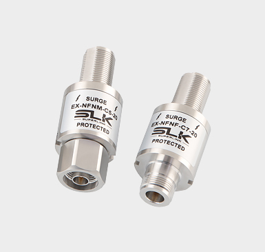
Millimeter wave connectors 3.5mm, 2.92mm, 2.4mm and 1.85mm products are widely used in optical communication, IoT instrumentation and radar systems;
18GHz high-frequency BNC products are used in radio and television systems, 4K, 8K high-definition and remote video communication;
SMP, SMPM, SMPS series ultra-miniature blind mating products, mainly used in military industry, semiconductor communication, optical communication and security system;
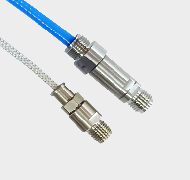
Low-loss phase-stable cable assemblies are widely used in radar communication and transmission systems;
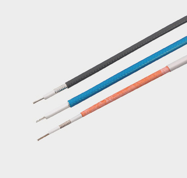
Integral armored cable assemblies are used in harsh environments and long-distance transmission systems;
Semi-steel and semi-flexible cable assemblies are used in 5G communication equipment, quantum communication and instrumentation, etc.