Passive intermodulation measurement technology
 2023-12-08
Due to the severe attenuation effect that affects the operation of communication networks, PIM is receiving increasing attention in the field of wireless communication. Whenever signals of two or more frequencies encounter a nonlinear electrical junction or similar substance, intermodulation will occur. The result is the generation of unwanted signals, whose frequency can be calculated from the original frequency, which can lead to a decrease in system capacity and/or a decrease in call quality.
In the reality of emphasizing cost-effectiveness, blindly adhering to the principle of "low" intermodulation is difficult to meet the large demand of the market.
Due to the fact that frequency depends on the characteristics of many devices and their subsystems, a fixed frequency testing method may not be suitable.
The reasons for the formation of PIM
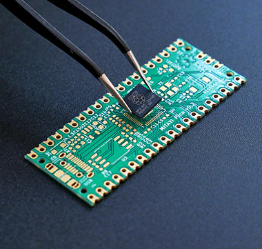
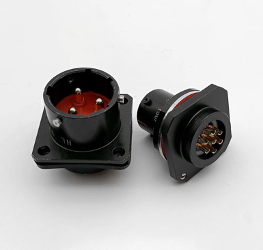
Once you have well-designed and well manufactured components, the next challenge is assembly and system installation. All nodes are potential producers of intermodulation, therefore, each connection point is a potential source of problems. Testing nodes in a good external environment is still unreliable when there is mechanical pressure (bending of the cable, torque load on the joint section, joints exceeding/below torque).
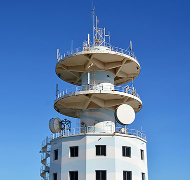
Furthermore, natural factors are the natural enemies of the network parts exposed to nature. Swinging caused by wind, daily temperature changes, various forms of humidity, heat load caused by sunlight, and dust in the air. Each of the above situations will destroy the quality of the device in the network and ultimately lead to channel collapse. The attenuation of seams, separation of nodes, invasion of moisture, oxidation of materials, and contamination of dust will all increase intermodulation and reduce receiver sensitivity. This result is based on the actual situation of cellular networks under the design potential.
Good communication quality requires maintaining a tolerable carrier to interference (C/I) ratio, therefore, our goal is to minimize interference (I) as much as possible. In an ideal situation, the interference "I" is always smaller than the receiver's background noise. One of the reasons why we don't want to see interference is passive intermodulation.
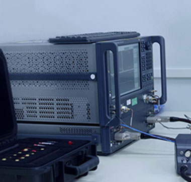
The usual practice for measuring PIM in the past was to inject two fixed frequency, 20 watt continuous wave signals into the testing environment, and measure the resulting intermodulation power value. This scheme is consistent with the method for measuring PIM defined by the International Standards Committee (IEC TC46 WG6).
Based on an understanding of the implementation methods (and related shortcomings) of PIM measurement, Summitek has set the following design goals: to establish a set of testing equipment with high-quality and repeatable testing methods. Make the device easy to establish and use. By providing new and useful tools to ensure the world's advanced level. In order to establish a clear implementation basis for comparison, standardization will be introduced into this complex testing method. Keep up with current technological trends and testing standards. Listen to consumer suggestions and merge them into categories to provide the most comprehensive and easy to learn testing equipment as much as possible.
1. High integration design: Assemble all RF devices in a separate chassis to minimize the number of external components, which will improve the reliability, stability, and repeatability of the equipment.
· Simultaneously measuring multiple intermodulation products.
· The frequency sweep measurement characteristics of intermodulation verify the execution of the entire specified frequency range.
3.Creative new testing performance: The final device operation is simple, efficient, and rigorous, therefore, this testing method is very practical for ensuring product quality and network integrity.
Most measurement methods are based on a pair of independent carrier frequencies. Due to wireless communication standards, this frequency is often set at the edge of the transmission frequency band.
Taking devices operating in the PCS1900 frequency band as an example. Typically, carrier 1 is set to 1930 MHz and carrier 2 to 1990 MHz for testing (note: some passive intermodulation testing equipment must set one carrier within the receiving frequency band and the other within the transmitting frequency band due to design reasons. The correctness of this testing method is controversial). After determining the transmission frequency and power, and setting the spectrum analyzer to intermodulation response, the test begins. During the testing process, it is important to avoid colliding with the tested device and testing instrument to avoid data spikes caused by the instability of the spectrum analyzer when scanning through the intermodulation frequency band.
Experience has taught us that this method of measuring passive intermodulation has many limitations and hidden potential issues.
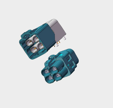
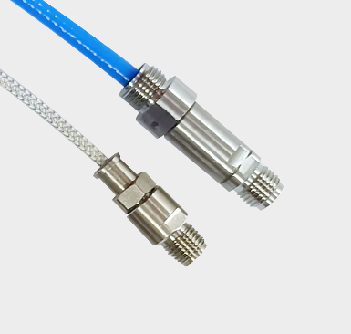
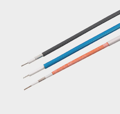
The issue of dynamic measurement in cable assembly has received great attention. We must pay attention to the intermodulation generated by the joint/cable interface, and also consider the intermodulation generated by the cable itself (caused by micro cracks on solid conductor cables and discontinuous contact of braided cables). The test includes intermodulation when the cable is in a bent state or when the joint/cable surface is in a twisted state.
In our view, in wireless communication networks, all components of the base station transmitter are subject to intermodulation. Summitek uses two testing methods to perform passive intermodulation testing on all tested devices using Summitek's analyzer. These two methods are "tapping" experiment and "deflection" experiment, respectively. The "tapping" experiment is simply tapping the device and observing the intermodulation response. For example, frequent tapping on the adjustment screw of the filter can produce high intermodulation values. After stopping the tapping, the intermodulation value sometimes returns to its original low intermodulation state, while sometimes it still maintains a high intermodulation state. The "tapping" experiment is very useful in proving that shielding devices and cables will eventually fail.
In the following examples, we will have a test chart as an explanation. In this experiment, we used a Summitek analyzer with strip recording paper function to record the intermodulation response data during the experiment. The tested device is a PCS1900 bandpass filter, and we are concerned about the intermodulation changes caused by tapping. Another experiment afterwards was conducted to demonstrate that the intermodulation index of the device rapidly deteriorates when the temperature changes.
The "deflection" experiment is to observe the changes in intermodulation when an appropriate lateral force is applied to the joint of the tested device. Insufficient fixation of the connector on the device body or weak internal emission structure can lead to intermodulation.
So far, the accepted method for measuring passive intermodulation is to set the carrier wave to two fixed frequencies and measure the resulting intermodulation. These two fixed frequencies are usually set in the transmission frequency band, but they may not necessarily be so. We found that this testing method is not very appropriate for the intermodulation measurement of a large portion of devices. Because the intermodulation characteristics of these devices vary with a frequency dependent function. The intermodulation testing equipment produced by Summitek's passive intermodulation analyzer has a multi band scanning function, which solves this problem and is simpler and more practical.
Here is an obvious example to demonstrate the advantages of a frequency sweep intermodulation tester. In the experiment, a duplex device in the PCS1900 frequency band with faulty connectors was tested. It should be noted that the damage to the connector of the device is caused by excessive torque, and it cannot be detected by visual observation and frequency sweep measurement of echo loss. The following diagram is a comparison diagram of the return loss between a "good" duplexer and a "bad" duplexer.
A "good" duplexer has reached the technical specification of -115 dBm throughout the entire frequency band, but when the transmitting carrier of a "bad" duplexer is shifted from the passband edge, its intermodulation index rapidly deteriorates. If these two duplexers only use the carrier at the passband edge for testing, they can both pass the quality evaluation screening.
In order to fully display the characteristics of the tested device, Summitek's passive intermodulation analyzer with frequency scanning function records the intermodulation value of each carrier in the entire transmission frequency band (i.e. downlink) when each of the two channels is scanned. However, each time only one carrier is in the scanning state, while the other is maintained at a fixed frequency at the passband edge. In the following example, when carrier 2 is scanned in the frequency range of 1950 to 1990 MHz and carrier 1 is fixed at 1930 MHz, the frequency range of the third-order intermodulation signal generated is between 1870 and 1910 MHz.
The measurement results can be recorded in a document and copied to the computer's clipboard so that they can be pasted into another application or hard copied directly to the printer for printing.
Due to the commitment of wireless communication service providers to maintaining and winning customers, controlling passive intermodulation distortion is directly related to the economic interests of service providers. The current passive intermodulation in cellular networks affects the capacity and call quality of base stations. Therefore, in order to achieve better network performance, the passive intermodulation index must be valued, measured, and controlled throughout the entire design, manufacturing process, and even after installation at the base station.